
- #VISUALDESIGNER VS XDIAGRAM SOFTWARE#
- #VISUALDESIGNER VS XDIAGRAM SERIES#
In this example, I'll cover one feature: logging into the system. Principles and, as a consequence, is difficult and costly to maintain
#VISUALDESIGNER VS XDIAGRAM SOFTWARE#
Software doesn't follow the S.O.L.I.D.Missing functionality for a specific feature.If you encompass too much, you take on many risks, including: In any model, the one thing you want to avoid is “Boiling the ocean.” In other words, you want to be very focused on a specific feature. The user is now authenticated and is now logged into the system.The user is re-directed back to the system.

 The user authorizes the system with the provider. The user logs into the selected provider. The user selects the authentication provider (Facebook, Twitter, Google or Microsoft). The user navigates to the system via a Web browser. To illustrate the UML Diagrams that make up the models, I'll focus on one aspect of a larger system: authentication and logging into the system with one of four providers: The following are good resources for more information on these tools: The UML Diagraming tools presented in this article are very feature-rich. Second, this article is but a brief introduction. Like anything new, incorporate additions to your toolbox gradually. You don't need to use all of these diagrams all the time to be successful. There are two points to consider before moving forward. Component: Illustrates, in a high-level fashion, the physical parts of a software system.Ĭollectively, these diagrams illustrate what your problem domain is and what makes up the various elements that comprise the solution to the problem. Actors and software components are capable of performing these actions. The system will be capable of performing these actions.
 #VISUALDESIGNER VS XDIAGRAM SERIES#
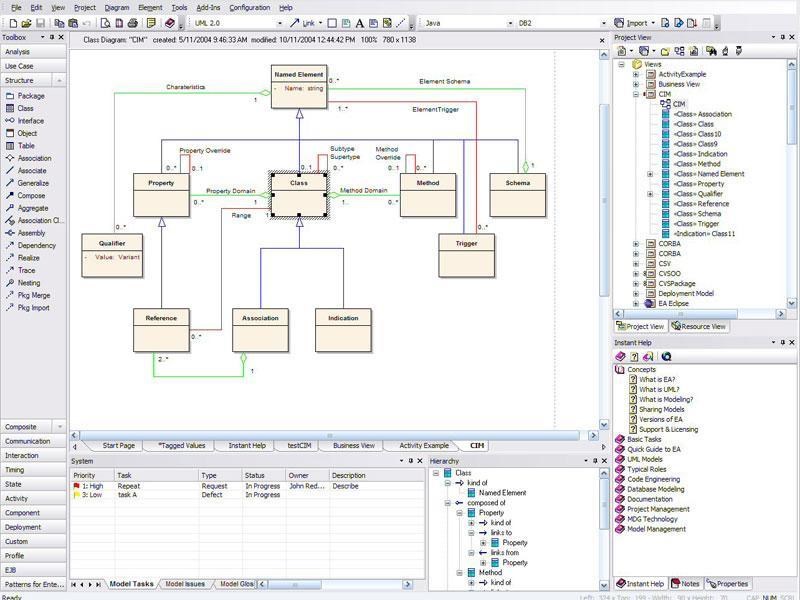
Activity: Illustrates a business or software process as a series of actions. Sequence: Illustrates the sequence of messages between classes, components, subsystems, and actors. Class: Illustrates data types that make up the system and the relationships amongst those types. Use Case: Illustrates the actors and their interactions with the system. There five UML 2.0 Compliant Diagrams that ship with Visual Studio Ultimate are: The UML Diagrams are a great way to support Agile Planning through their integration with Visual Studio Team Foundation Server. You can do so without getting into the details of how a solution is implemented.Īs you will quickly see, like the Dependency Graph and Layer Diagrams, the UML diagrams are not static. In other words, you can describe what comprises the solution. Through diagrams, you can illustrate and describe elements that comprise a solution to the problem. Diagrams help quantify what will eventually lead to how the problem at hand will be solved. Before you can determine how a problem will be solved, you first have to determine what problem you are trying to solve. There are two necessary concepts to keep in mind: I'll employ various diagrams (Dependency, Layer, and UML) to illustrate the models. I'll steer clear of implementation details. Modeling is not about getting into the details of how the solution will be developed. Before getting into the details, it's important to emphasize that modelling is about describing the problem domain and the components that collectively address the problem domain. In this second part, I complete this series with an introduction of the UML diagrams that ship with Visual Studio Ultimate. The Dependency Graph provides a quick and easy way to get both high- and detail-level views of the dependencies among the components that make up your application. In Part 1 ( I introduced two powerful Visual Studio modeling tools: the Dependency Graph and the Layer Diagram.


 0 kommentar(er)
